
Dimmers are instruments which controls the. It has also found application in microscopes for this purpose.

Pin On Mini Projects
PWM system April 18 2021 909pm 1.

. The slide moves from position x 0 to x 1 and the resistance up to slide position x is proportional to x the total resistance is Rpot 100Ω at x 1. Its a basic implementation of a light dimmer. Other than just varying resistance the potentiometer can.
The TRIAC circuit above is already a light dimmer. A rheostat that is used to vary the intensity of a domestic electric light. How to make light bulb LED dimmer without variable resistorJust using N channel mosfet and push buttonhope you like this circuit.
When using resistors youll need to know the power required for your project so youll calculate this using a LED resistor value formula like this one. My goal is to be able to manually dim this MyLamp by slowly bringing the signal down with. Maximum current draw is in the 004 A range.
Now what if instead of a variable resistor we use an. Homework Statement Some light-dimmer switches use a variable resistor as shown in figure. But normal resistors have a fixed resistance which cannot be varied.
Hello I have a passive device lets call it MyLamp see attached which requires 65V 60AC when fully turned on. You might be familiar with resistors and their ability to reduce current as well as voltage. Current through a light source.
Strictly speaking a light dimmer would not affect the speed of the motor because the motors speed is directly related to the frequency of the supply and the dimmer doesnt affect the frequency. This is why a potentiometer can sometimes be referred to as a Variable Resistor. For that microscope a microscope rheostat- is used.
The potentiometer adjusts a control voltage which controls a TRIAC where the TRIAC is switching ON for a certain fraction of each AC wave then OFF for the rest of the wave repeat for each cycle of the AC. Potentiometers are three terminal devices which have the ability to vary their resistance. Ad Bestellen Sie noch heute ihren Dimmer auf Elektroshopwagnerde.
Sic way of controlling current is to connect. This light dimmer circuit is built with various electrical and electronic component s like resistors R168 kilo ohms R2280 kilo ohms and R310 kilo ohms variable resistors VR1100 kilo ohms and VR2200 kilo ohms capacitors C1 C2 and C3033 uF400V TRIAC is BT136 and DIAC is ER900. Varying the resistor R1 in the circuit will vary the firing delay angle.
General led dimmer or brightness control circuit using photoresistor transistor and variable resistor Main functionality of the above traditional light dimmer circuit Current passing through LDR increasesdecreases depending on the amount of light thrown on the light detector. Im assuming you are talking about a fan with an AC induction motor. Answer 1 of 11.
An electrical resistor with two terminals whose resistance is continuously variable by moving a knob or slider. Using a rheostat will serve the purpose. A potentiometer is a variable resistor with a knob that allows you to alter the resistance of the potentiometer as you turn it.
But if you introduce some resistors in parallel the picture changes. Resistors all ¼-watt 5 Carbon R 1. R 2 and C 3 used to overcome interference problem.
Light Dimmer Circuit Using Triac. Ihr Fachhändler seit 15 Jahren - bestellen Sie jetzt online zu fairen Preisen. A variable resistor consists of a piece of resistive material a stationary contact arm and a moving contact arm.
Answer 1 of 4. The greater the alpha the less power the load receives. From main supply capacitor C 2 get charges which trigger DIAC D 1.
You could do all the math but really its just easiest to stick it on a. Lower is the value of the resistor R1 and faster the capacitor C1 charges. Early dimmer switches had a pretty straightforward solution to adjusting light levels -- a variable resistorAn ordinary resistor is a piece of material that doesnt conduct electrical current well -- it offers a lot of resistance to moving electrical charge.
A variable resistor serially to the light source. VR 1 is used for fine brightness controller which control brightness to lower level. Arduino AC Voltage Dimmer Variable Resistor.
While studying a specimen using a light microscope it is necessary to observe any sample using various light intensity to get an enhanced and different view. A dimmer circuit changes the intensity of the light. David isnt wrong that if you just had one variable resistance in series with the resistor adjusting it wouldnt seem very linear in relation to perceived brightness.
The capacitor C1 is charged across the R1 variable resistor. I tested these values with a red LED and it works pretty great. Ad Riesenauswahl an Werkzeug und Baumaterial.
The basic principle of light dimmer is based on phase control. But for the sake of convenience dimming an LED is just a matter of adding resistors but this largely depends on how bright your LEDs are in their original state. A potentiometer is used but not in the way youre thinking.
In this project youll create a dimmer switch by adding a potentiometer to control the brightness of an LED. If a light bulb or an LED is a load then its light will dim as we vary the gate voltage. The variable resistor VR 2 is main controller of the circuit Light Dimer.
When the C1 reaches the breakover voltage of DIAC 30V Q1 starts conducting the voltage is applied to the TRIAC gate and it triggers U1.

Fan Regulator Circuit Ac Lamp Dimmer Ceiling Fan Electronic Regulator In 2021 Circuit Regulators Dimmer

4000w Ac 220v Scr Voltage Regulator Speed Controller Dimmer Thermostat Module Ebay Voltage Regulator Diy Electronics Motor Speed

100w 50 Ohm Ceramic Wirewound Potentiometer Variable Resistor Light Dimmers Electrical Equipment Arc Lamp

Dc Light Dimmer Using Bd139 Npn Transistor 0 38v Maximum 3a Negative Voltage Control Youtube Diy Electronics Electronics Projects Pic Microcontroller

Fan Regulator Circuit Ac Lamp Dimmer Ceiling Fan Electronic Regulator In 2021 Circuit Dimmer Regulators

An Led Array Pwm Dimmer With The 555 Led Dimmer Smart Lighting

Light Dependent Resistor Ldr Project Electrical Schematic Symbols Ldr Light Ldr

Triac Lamp Dimmer Circuit Are Devices Used To Lower The Brightness Of A Light Electronics Basics Electronics Circuit Dimmer
Pin On Chargeur Batterie

Ac 220v 2000w 8a Scr Motor Speed Controller Voltage Regulator Dimmer Thermostat Ebay Voltage Regulator Motor Speed Electronics Mini Projects

How To Make Light Dimmer Circuit 220v Ac Using Bta24 Triac Youtube How To Make Light Dim Lighting Circuit

Easy Ac Motor Controller Ac Light Dimmer Circuit Youtube Dim Lighting Electronic Circuit Projects Computer Power Supplies

Voltage Controlled Dimmer With An Attiny85 Electronic Schematics Electronics Circuit Arduino

Light Simmer Circuit 1000 Watts In 2021 Light Circuit Watts
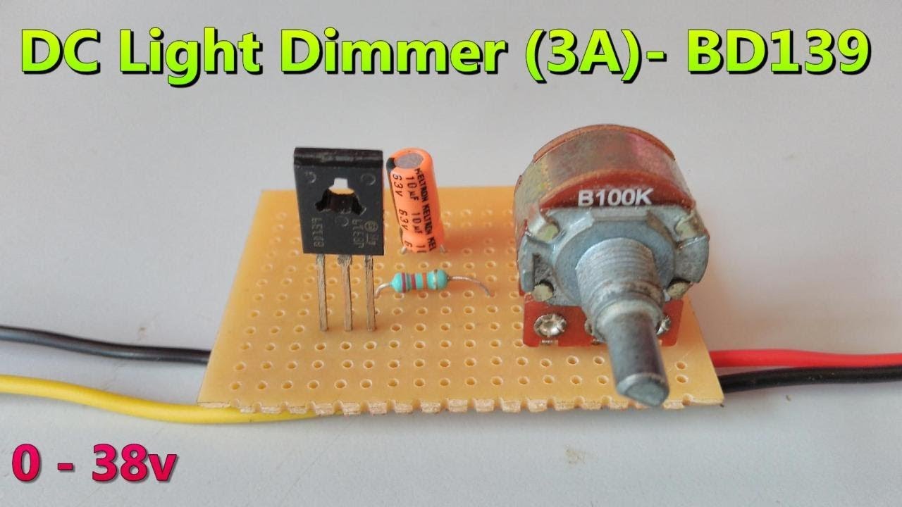
Dc Light Dimmer Using Bd139 Npn Transistor 0 38v Maximum 3a Negative Voltage Control Youtube Diy Electronics Electronics Projects Pic Microcontroller

Simple Light Dimmer Circuit Electronics Technical Hub Dim Lighting Circuit Diagram Circuit

Potentiometer Cube In 2021 Cube Dimmer Switch Stem Teacher

555 Pwm Led Dimmer Circuit Diagram Power Battery Saving Eleccircuit Com Circuit Circuit Diagram Led Dimmer

Electric Fan Motor Speed Control Circuit Using Triac Circuit Circuit Diagram Electronics Projects
0 Response to light dimmer variable resistor
Posting Komentar